Electronic Design and Family Site
Curing RFI in the "Lazure" Keyboard Keyer
Years ago, I discovered that I needed an easier way to transmit CW info during contests. After a brief search, I decided to get a keyboard keyer kit from Jackson Harbor Press. I built the kit and it worked wonderfully
-But-
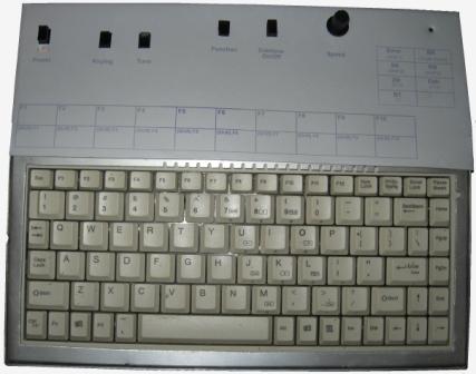
A full-sized keyboard didn't fit very well on my radio desk. Thus, I bought a miniature keyboard at a traveling computer show. It was inexpensive and fit my desk well. I plugged it into the keyer, fired it up, and lost the 15M band to noise. A quick check revealed that the new keyboard was spewing RFI on every band; effectively eliminating 15M and limiting reception in many areas of the remaining bands.
This led to the solution described in this article:
-Optically isolating all input and output signals.
-Decoupling power connections.
-Shielding the entire keyer into individual sections, keyboard and all.
The most effective way I could think of to incorporate the signal and power decoupling was to design my own PCB and place the keyer's components on it.
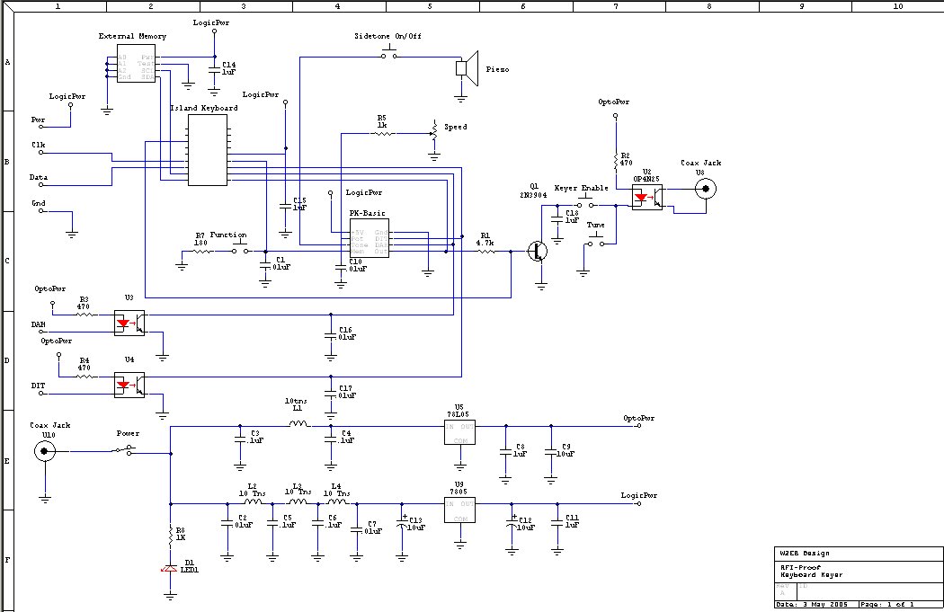
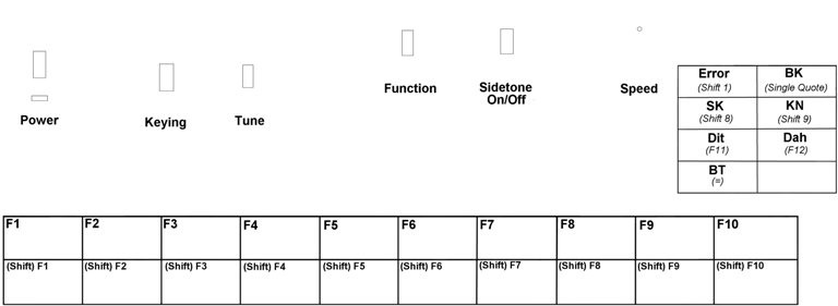
Power enters at the DC coax jack and is enabled through the power pushbutton switch. Input power can range from about 8 volts to as much as 16 volts. When enabled, the power lights the "Power" LED which is current-limited through resistor R8. The power is then run through two series of LC filters: one for Logic power, and one for Opto-isolator power. The LC filters effectively decouple any internal noise from the incoming DC preventing that noise from being introduced onto the DC line. These two separate DC paths then feed two separate regulators. Using two separate regulators helps separate any noise generated in the logic circuit from the actual keying circuits.
The Island Keyboard interface IC performs two functions: it converts keyboard commands into paddle closures for the keyer IC, and it controls the extended memory stored in the Memory IC. Its operation can be found here.
The PK-Basic Keyer IC handles all keying and timing functions. It's inputs are the paddle switches and memory switch, and its output feeds the Keying Transistor through resistor R1. The keying speed is controlled by the Speed Potentiometer which can vary the speed from about 7WPM to over 39WPM. This IC also sets and contains basic settings and memories. See the operation manual for details.
The output of the keyer IC is also sent through an opto-isolator to further isolate the keyer from the rig to which it's attached. Since the maximum keying speed of this circuit is only 39WPM, a typical opto-isolator can easily handle the bandwidth. Switching is provided to disable the output and enable it while ignoring the keyer output for tuning purposes.
If your rig's sidetone is unacceptable, a speaker output is also provided and can be turned off via a "mute" switch as necessary.
The entire circuit including keyboard is contained in an aluminum chassis to provide shielding. The only exposed parts are the keys of the keyboard, the speed pot shaft, the power LED, the switch shafts, and the power, paddle inputs, and keying output.
This is the PCB labeled as if viewed as an X-Ray from the topside
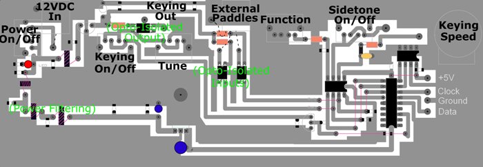
This is the raw PCB as if viewed as an X-Ray from the topside

The Chassis - Shielding
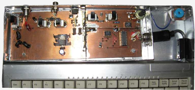
This view best illustrates the enclosure & shielding scheme I used in this project. I don't expect that anyone will try to duplicate my enclosure; it's very custom. I made this page to illustrate the isolation of the various stages within the project.
-The compartment at the far left contains total circuit I/O: the Input DC, Input Paddle connections, and output keying line.
-The compartment at the top right contains only the piezo speaker and its switching. I feared that the Square wave feeding that might bleed into other circuits.
-Finally, the compartment at the lower right is the Logic section. This was specifically isolated to prevent digital signals from leaking out of the chassis into my receiver.
Also note that the keyboard cable is wrapped by a snap-on ferrite core. This keeps signals from the keyboard out of the keyer.
The chassis itself is constructed of aluminum and all joints are riveted. The cover (not shown) is also sheet aluminum bent to simply rest over the compartments. The walls between the various compartments are made of steel and soldered to the PCB.
Faceplate Artwork