Electronic Design and Family Site
A Portable, Rugged LCD SWR Meter
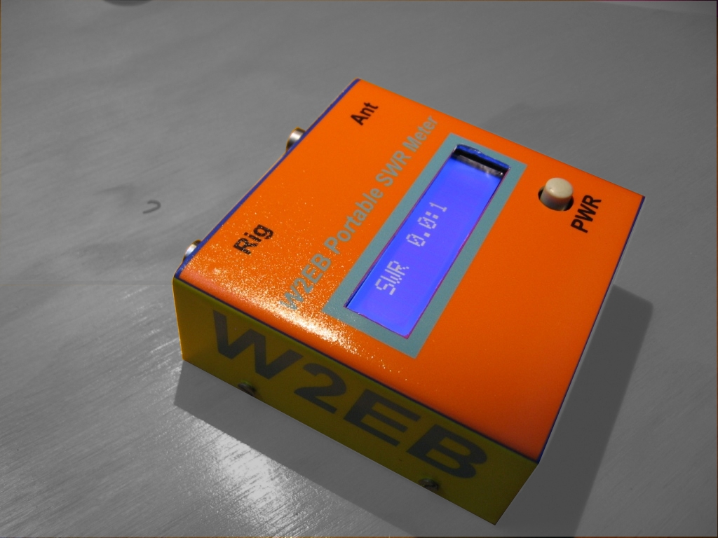
My Field Day effort this year pointed out to me that some of my equipment is simply too big, heavy, or fragile to use for my portable "GO" kit. One of the items I've been including in the kit, a dual-movement analog SWR meter designed and offered by the North-Georgia (NoGa) QRP Group that I obtained and built during "Four Days in May" (FDIM), a QRPers event held in conjunction with the Dayton Convention, died on me this year. The "Reverse" needle stuck at zero and refused to move, rendering it useless for me. I had to do better. I toyed with the idea of using an LED display, but the load on a battery and the physical size of such a unit made it impractical. All that was left was an LCD unit. Thus was born the Handheld SWR Meter for the "GO-Kit".
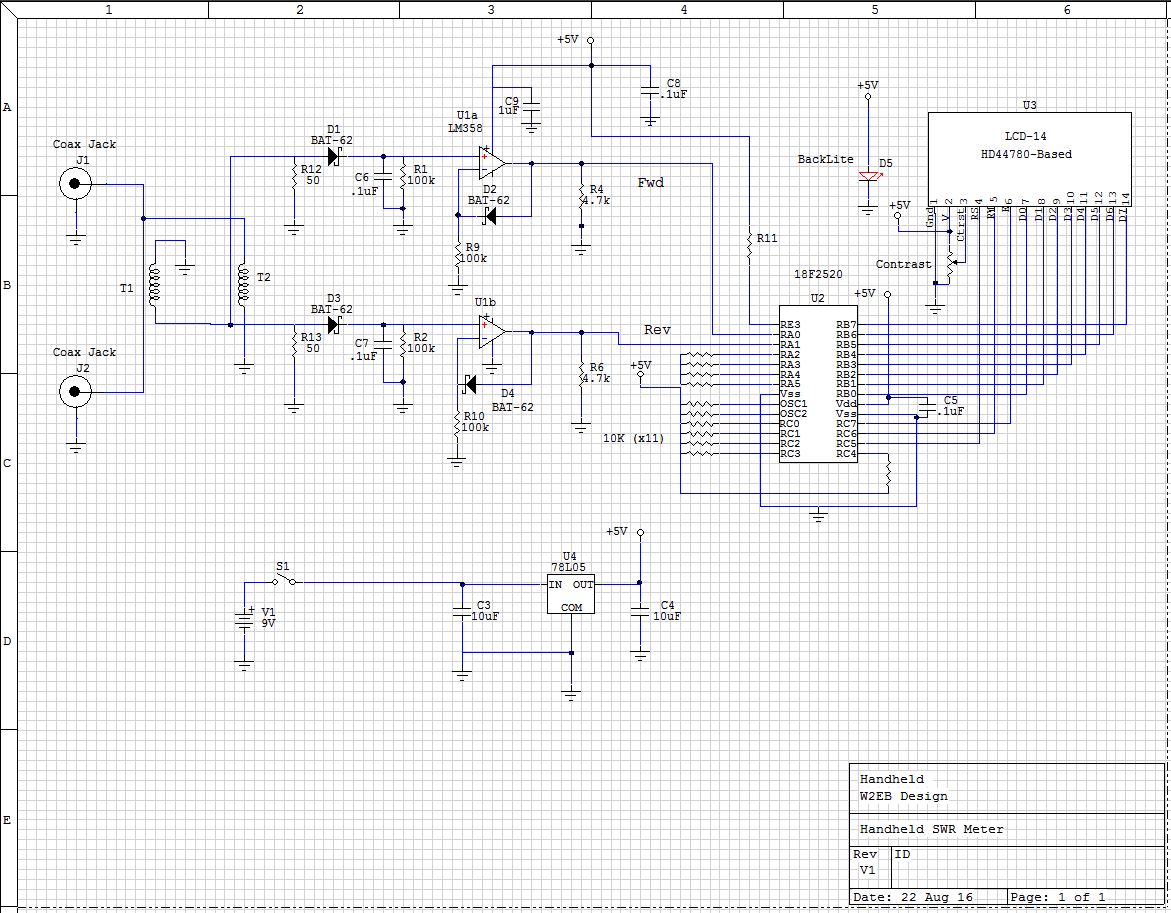
I copied the schematic of my Bench SWR Meter except that I removed the buffer amplifier between the first amp and the ADC inputs on the PIC; it didn't seem necessary. The prime change from the original design is size. This unit was designed to be much smaller.
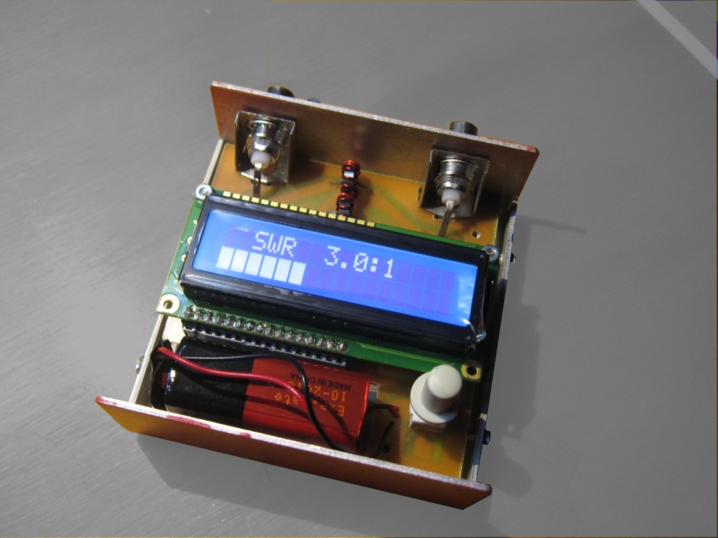
As for every other attempt at portable equipment, I tried to ruggedize the device by not wiring anything. I wanted every device, I/O, and control attached to the circuit board. The only thing on wires is the battery clip. I would have had to waste a lot of chassis-space putting the battery clips directly on the board itself.
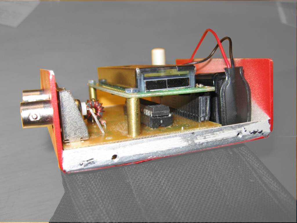
The transformers are attached both with their multi- windings, and via the single "turn" that is actually a cut lead from a thru-hole component run through the toroid and soldered on pads on either side. By pulling that lead tight to the board, the toroid is very well captured.
The final unit came in at 3.25" x 3.5" x 1.3". Nearly 1/4 of that size is the battery: the PCB is 3" x 3".
Just like for the Handheld Antenna Analyzer, I used three unique construction techniques; a couple I've used a few times over the years, and one brand new to me:
-Plasti-Dip. Plasti-dip is a rubberized goop that is designed to cover tool handles for improved grip. I use it to "paint" aluminum! As the finish on aluminum chassis, it adheres: something that few ordinary paints can claim, and it provides an actual rubbery-protective coating that cushions shocks to the piece itself.
-I used my "sticker" as a faceplate. I made the sticker using the technique shown here, then stuck it on the substrate face of the chassis.
-Brass standoffs. Rather than run hardware through a board using hollow standoffs and nuts, I use threaded brass standoffs and solder them to the bottom of the PCB. This saves the weight of longer screws and nuts, and the hassle of having to attach nuts on the PCB.
I also used something totally new to me: Connectors for the LCD. Previously, I would just run jumper-wires between the PCB pads and their corresponding pads on the LCD. While that worked well enough, if I ever had to replace the LCD or move it well away from something for troubleshooting or component replacement, it was a lot of work and risked damaging the LCD module. This time I used a 16-pin header and socket. That forced me to use standoffs to support the opposite side of the LCD module. The picture below shows both the connector (Black, near the battery), the standoffs, and the PIC located under the LCD module; thinking in 3D helps reduce the overall footprint of the device.
The Schematic
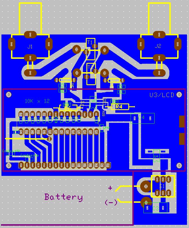
PCB Layout, Bottom Layer Only