
Electronic Design and Family Site
A Portable Field Keyer
During Field Day this year, I discovered a "weakness" in my equipment. The only way I had to verify that my electronic touch-paddles were operating was to actually key my transmitter. The transmitter is battery operated, and needlessly transmitting wastes that battery. Not a good idea. I needed a keyer!
I had a keyer IC (PKBasic from Jackson Harbor Press) that I purchased years ago to put in my Keyboard Keyer, but with the advent of logging programs that output CW on the serial port of computers, I hadn't used the keyboard keyer in years. As a happy coincidence, the PKBasic runs off 3V, making it ideal for portable operation!
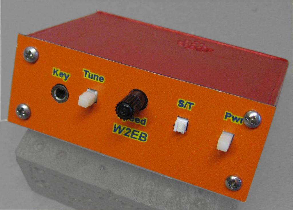
The keyer I made is mainly a support package for the IC, but it adds some features that are fairly important to me...switchable Sidetone, an output "Tune" switch, and Output Isolation using an opto-isolator. The tune switch allows me to constantly key my transmitter for testing SWR; something the transmitter can only do by going deeply into its menu structure.
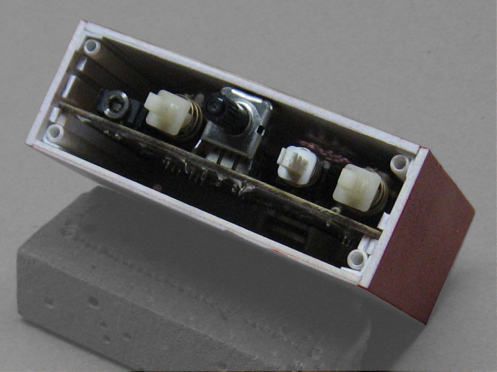
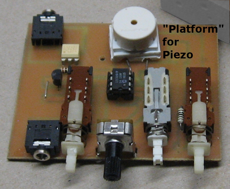
Since I wanted this to be as rugged as possible, I also wanted all parts and controls to be mounted directly to the PCB...no wires. Typically, battery connections MUST be wires, but in this case, using a 3V battery allowed me to use a coin-cell and mount its holder directly to the PCB. Thus, other than the Piezo which had to be mounted away from its pads, every component is board-mounted directly (and the Piezo is supported by the block shown below).
I'm particularly proud of a couple of aspects of the assembly that I discovered and implemented:
-Plastic construction
I have built one other chassis of plastic, the container for my portable battery pack, but that was nowhere near as inventive as this. as the picture shows, I added "rails" to slide the PCB into the chassis, and added plastic tubes that are sized just perfectly to screw number 4 screws into snugly...as good as using tapped holes. These two additions made this chassis better even than metal for this application. Once I fused the seams properly, this chassis became quite strong.
-Plasti-Dip as paint
Plasti-dip a rubberized goop that is designed to cover tool handles for improved grip. I used it to "paint" this chassis! I could have used any color paint I wanted, but decided to plasti-dip this chassis for 2 reasons: the plasti-dip provides some shock absorption if I drop the device. It doesn't offer much, but any is better than none. Then, it also encapsulates the chassis. I hope that the encapsulation provides some mechanical strength that glue alone doesn't. I haven't used plastic chassis construction much before and don't fully trust it yet. I hope the plasti-dip encapsulation will make up for any failings of a glued sheet-plastic chassis.
You'll note the plastic block under the piezo speaker. When resting on the PCB, the speaker was far from the holes that allow me to hear it. I needed a way to make the speaker rest higher than the surface of the board. Thus, this block. I stacked 3 pieces of 1/2" by 1/2" plastic and glued them together. I drilled holes for the leads, and the bottom layer has slots cut to direct the leads to the solder holes beside where the speaker actually mounts.
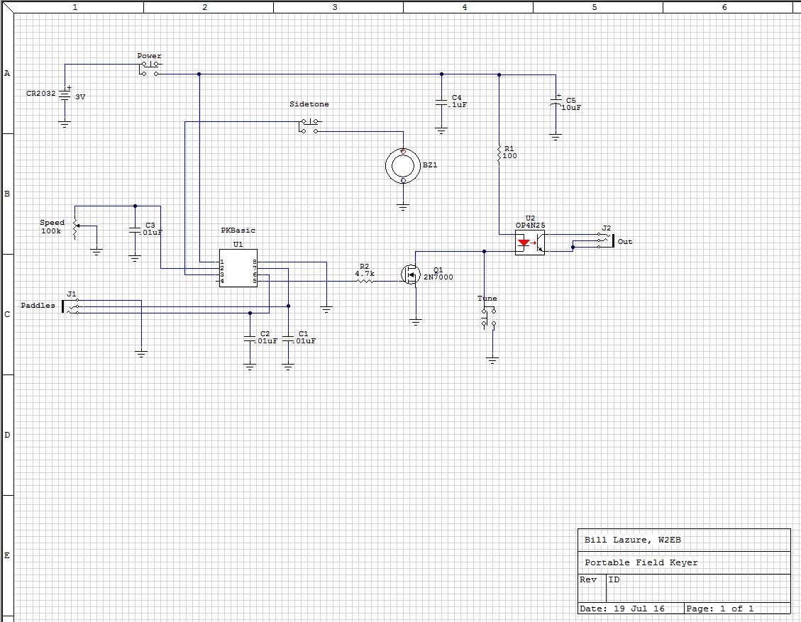
The Schematic
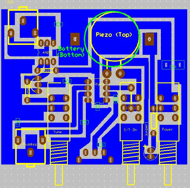
PCB Layout (Single-sided, Viewed from top)
Chassis Details
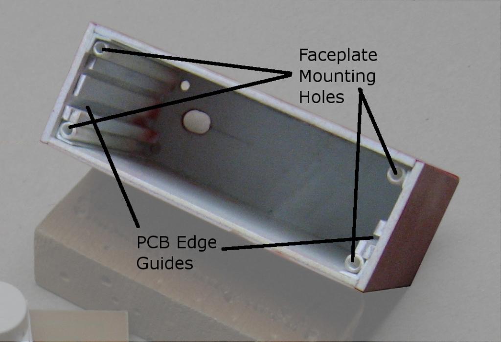
As I mentioned above, I had to build a plastic block on which to rest the piezo; I needed it nearer the holes on the chassis. This picture shows the construction and mounting of that block
-Bill Lazure