Electronic Design and Family Site

Experiments in DDS - PCB Layouts

Using AD9850 & AD9854 with PIC 18F2520

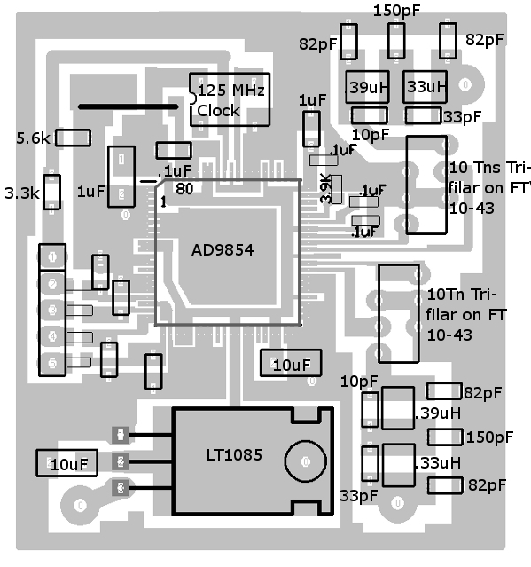
AD9854 RF Section without Digital control (Top-side view...the bottom is a solid ground plane)

Top view of the PCB for the Analog board of the AD9854-based DDS oscillator (the bottom is a solid plane)

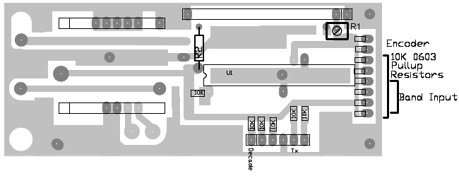
AD9854 Digital Section (Top-side view)

Top View of the PCB for the Digital Board of the AD9854-based DDS Oscillator

AD9854 Digital Section (Bottom-side view)

Bottom view of the PCB for the Digital Board of the AD9854-based DDS Oscillator

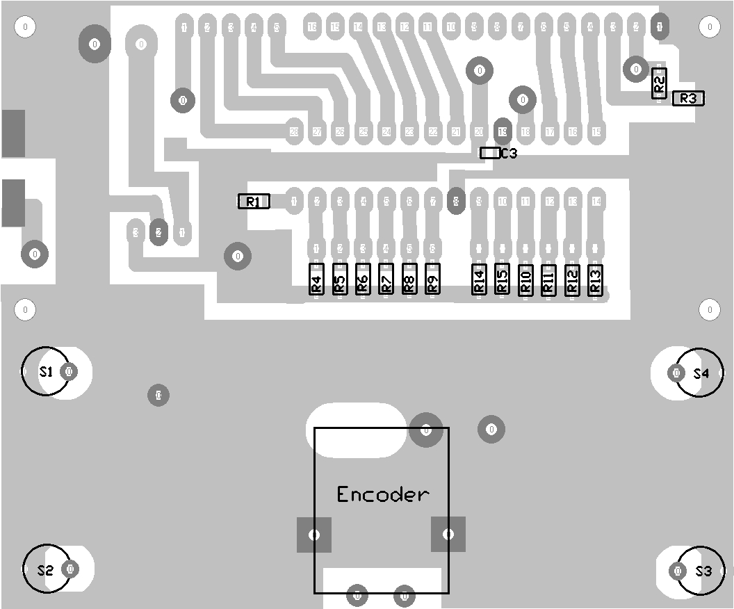
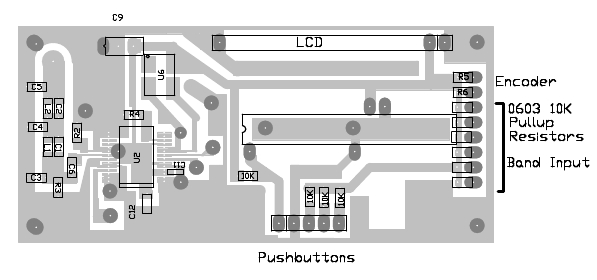
My "Test" DDS Board Top-side view

Top-Side view of the PCB for the AD9850-based DDS Oscillator

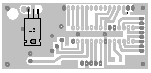
My "Test" DDS Board Bottom view

Bottom-side view of the PCB for the AD9850-based DDS Oscillator

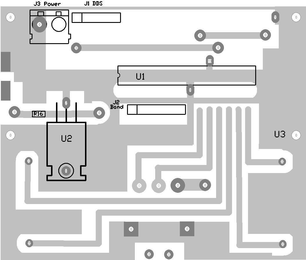
DDS Board with Commercial Module - Bottom view

Bottom view of the PCB for a DDS Oscillator using a common plug-in module

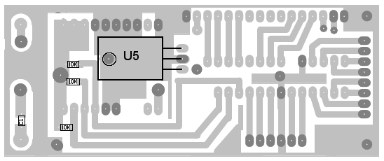
DDS Board with Commercial Module - Top view

Top view of the PCB for a DDS Oscillator using a common plug-in module